Origin: Open Additive Manufacturing
https://www.origin.io/
At Origin, I gained experience in design and quality engineering in the early release stage of the Origin One DLP printer. Origin One’s open materials network promises to expand the range and availability of materials in the additive industry.
Projector Quality Test Rig
Designed a test rig to detect keystoning and image translation during on-site quality testing with the contract manufacturer.
Design Overview
Locating features connect the mounting plate to the projector, centering a projection plate over the lens.
Using tolerance stacks, rods maintain an accurate throw between the lens and projection area.
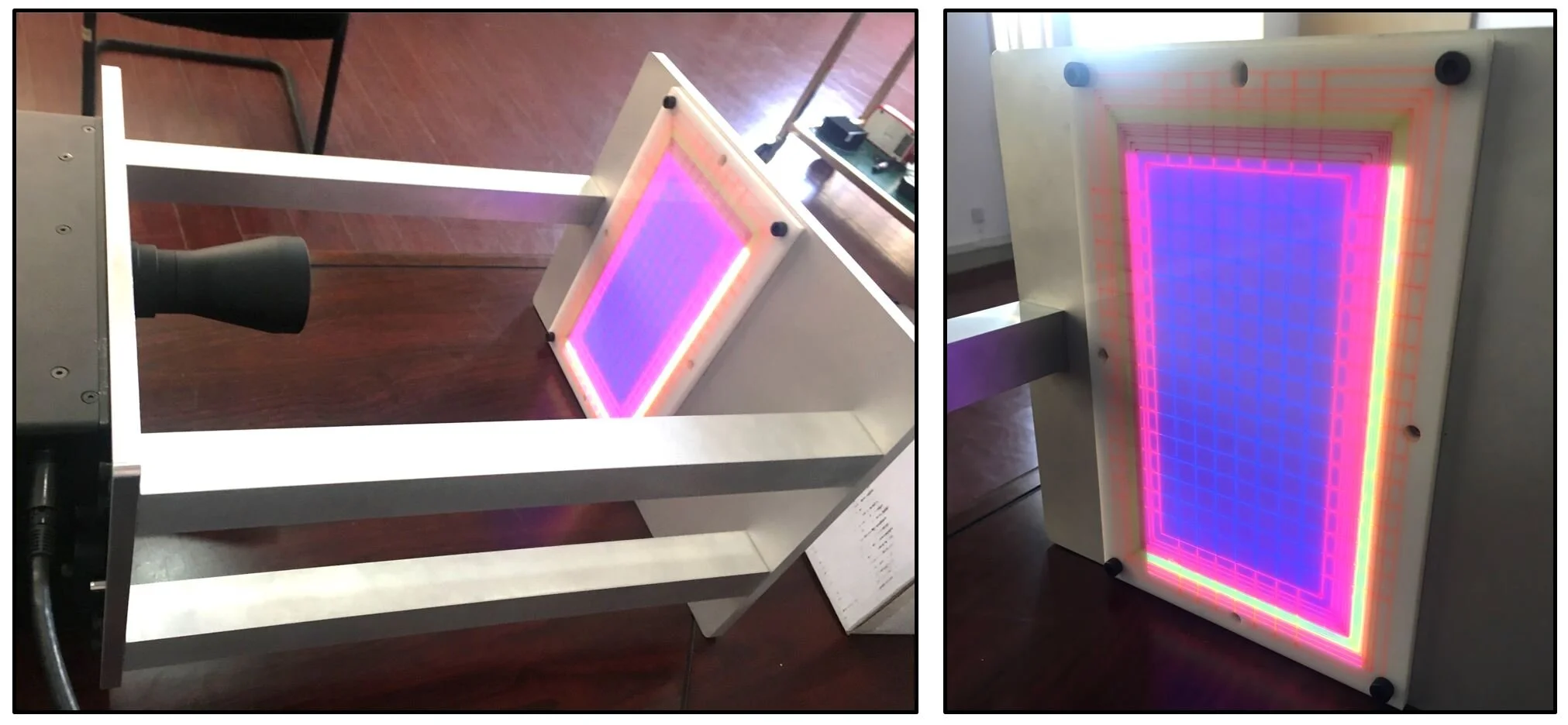
Errors bounds were calculated and laser etched into an acrylic projection plate. The lines were coated in UV reactive paint, color coded to various error boundaries.
When light is projected onto the plate, a quick visualization of error can be made.
The rig can be quickly assembled and dissembled, allowing for quick error analysis on-site at the contract manufacturer.

Results
Error visualization is depicted below, with the yellow light corresponding to image translation.
Using this rig, an image translation of 10mm from nominal was found at the manufacturing site, enabling critical improvements in quality control.
Lift Tooling
Developed a system to allow technicians to lift 150 lb printer to a table for installation.
Requirements: Lightweight, quick assembly/disassembly, can be shipped.
Performed structural analysis to determine plate deflection, generated technical drawings, calculated tolerance stacks, used version control software to manage components.
Design Overview
Four quick release pins on each handle assembly.
Bumpers protect printer from damage.
Quickly slots together with minimal tool usage.
Steel planks slide under printer and slot into feet to stabilize printer with quick assembly.


Quick assembly process depicted above, from top to bottom.
Minimal tooling and flat packing of components allows for on-site installation of printers.

Installation and use of lift system
Allows up to 150lb to be lifted to a table by two technicians
Linear Stage “Wobble” Test Rig
Design Overview
Developed a test rig to measure “wobble” along length of the linear drive, establishing a quality control system for new drives.
The z-movement standard deviation was derived from the standard print setting layer height.
A dial indicator was used to assess variation in motion on the z-stage actuators.
Designed a parallelism adjustment to normalize the slope for analysis.
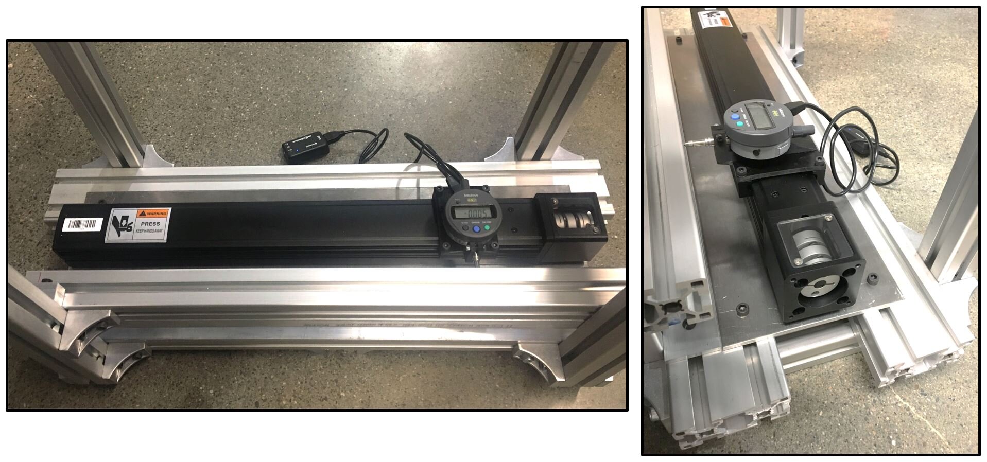
Testing Process
Each linear drive was mounted and installed into the test rig.
A 3D printed dial indicator fixture was mounted to the linear stage and the indicator installed.
During testing, the dial indicator touches off along a bar parallel to the linear drive.
The parallel bar is spring loaded and can be manually adjusted with a hex wrench to lie parallel with the linear drive, normalizing the slope.
Data was collected in excel and analyzed in MATLAB, allowing drives to be sorted for manufacturing priority and traceability.
